Leave Your Message

What Are High Order Filters and How Do They Work?

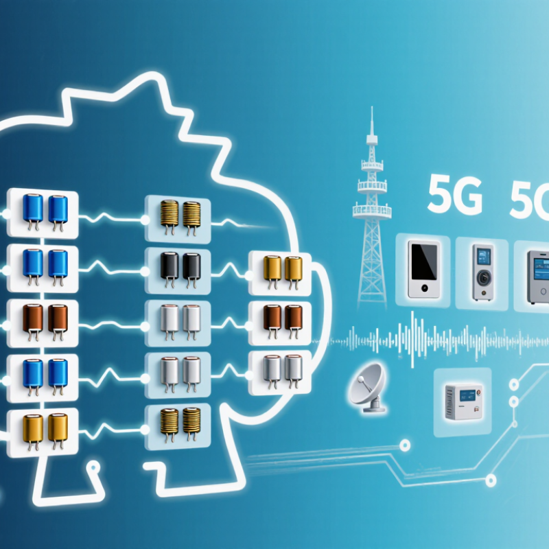
High Order Filters are precision networks designed to separate desired frequencies from unwanted energy. They appear in 5G radios, satellite links, medical instruments, audio equipment, and industrial measurement systems. Their “order” describes the number of reactive sections, or poles, shaping the filter response. More poles usually create a sharper transition between the passband and stopband. The trade-off is real. Higher order can also increase insertion loss, phase distortion, size, cost, and tuning sensitivity.

This technology matters because wireless systems now operate across crowded and highly regulated spectrum. The Ericsson Mobility Report, November 2024, forecast 6.3 billion 5G subscriptions worldwide by 2029. That growth increases pressure on front-end components to reject adjacent-channel interference while preserving weak signals. The same report forecast 2.3 billion 5G subscriptions by the end of 2024. Small frequency errors can therefore affect thousands of connected devices in one local area. 3GPP TS 38.104 defines demanding transmitter and receiver performance requirements for New Radio equipment. Filters help hardware meet those requirements, but they cannot correct every system weakness.

Engineers commonly evaluate insertion loss, return loss, rejection, group delay, quality factor, and temperature stability. A cavity filter may provide steep rejection in a base station. A ceramic or SAW filter may suit compact consumer equipment. The correct design depends on frequency, bandwidth, power, environment, and manufacturing limits. Industry market forecasts can differ, sometimes substantially, because suppliers define “filter” differently. That limitation deserves attention. This guide explains how High Order Filters work, where their performance comes from, and why a higher order is not automatically better.

What Are High Order Filters and How Do They Work?

Definition and Purpose of High-Order Filters

What Are High Order Filters and How Do They Work?

Definition and Purpose of High-Order Filters

A high-order filter is an electronic circuit that removes unwanted frequencies with several filtering stages. Its order equals the number of reactive components, poles, or mathematical sections in its transfer function. A first-order filter changes the signal by about 20 decibels per decade. A fourth-order filter can reach approximately 80 decibels per decade.

Sharper control matters.

The main purpose is frequency separation. A low-pass design can preserve slow sensor changes while reducing high-frequency noise. A high-pass design can block drifting voltage and retain faster signals. Band-pass filters isolate a selected frequency range, such as a vibration produced by rotating machinery. Engineers choose higher orders when nearby frequencies must be separated more aggressively.

However, steeper filtering creates trade-offs. More sections can increase phase shift, delay, component sensitivity, and circuit complexity. A sharp filter may also distort pulses that contain many frequency components. The ideal curve is never fully real. Component tolerances, temperature, and loading can move the cutoff point.

On a test bench, a designer may inject a swept-frequency signal and record the output with an oscilloscope or analyzer. This reveals passband ripple, attenuation, and unwanted resonance. I once treated a steep response as automatically better; that assumption was incomplete. The correct order depends on the signal, timing requirements, noise source, and allowable distortion. A carefully matched third-order filter can outperform a poorly tuned sixth-order design.


How Filter Order Shapes Frequency Response

What Are High Order Filters and How Do They Work?

A filter’s order is the number of reactive poles shaping its frequency response. Each added order increases attenuation beyond the cutoff. An ideal first-order filter changes by 20 dB per decade. A fourth-order design reaches about 80 dB per decade. That difference matters when unwanted energy sits close to the passband.

Sharper is not always better.

Higher order filters can create steeper skirts, but they may also produce ripple, phase shift, and transient ringing. In a laboratory sweep, a fourth-order low-pass filter may reject a 10 kHz interferer while preserving a 1 kHz signal.

However, component tolerances can move the cutoff point. My own design reviews often expose this weakness: calculated curves look perfect, while measured curves bend slightly at the corners.

Frequency response also depends on damping and topology. A Butterworth response stays flat in the passband. A Chebyshev response offers a faster transition, but introduces controlled ripple. According to IEEE Std 519-2022, systems below 69 kV commonly use a 5% total voltage harmonic distortion target at the point of common coupling. That figure does not define one filter order. It shows why engineers must measure the harmonic environment first. IEC 61000-3-2 also establishes harmonic-current limits for many low-current electrical devices. Therefore, selecting filter order requires more than counting poles. Load variation, phase behavior, thermal stress, and real measurements can overturn an elegant simulation.

Key Components and Signal-Processing Principles

High-order filters use several poles to shape signals more sharply than first-order designs. Each order adds approximately 20 dB per decade of attenuation. A fourth-order low-pass filter can therefore reach about 80 dB per decade beyond its cutoff frequency. Its key components include resistors, capacitors, inductors, operational amplifiers, and sometimes digital delay elements. Component tolerance matters. A 1% resistor can shift the expected response when several stages interact.

The signal-processing principle begins with the transfer function, H(s). Designers select a response such as Butterworth for a flat passband or Chebyshev for a faster transition. Higher order improves selectivity but often increases phase shift, noise sensitivity, and ringing. In practical audio and measurement circuits, engineers check cutoff frequency, stopband rejection, group delay, and quality factor. WSTS reported global semiconductor sales of 627.6 billion dollars in 2024, showing the scale of electronics where filtering supports sensing, conversion, and communication. Yet market size does not guarantee clean measurements.

Tips: Divide the filter into verified stages. Measure each stage before combining them. Use precision components near high-Q sections. Simulate temperature drift and tolerances, then test with a real oscilloscope. A fourth-order design may look perfect in software. It can still oscillate on a crowded circuit board. I have found grounding and layout problems surprisingly difficult to predict. ADC systems also need anti-aliasing before sampling, because unwanted frequencies can fold into the measured band.

Types and Applications of High-Order Filters

High-order filters use several stages to control unwanted frequencies. Their order describes the filter’s slope, not its physical size. A fourth-order filter, for example, changes signal strength faster than a second-order design. It can provide sharper separation, but it may also create more phase shift and circuit complexity.

Common types include low-pass, high-pass, band-pass, and band-stop filters. Low-pass filters smooth sensor readings and remove high-frequency noise. High-pass filters block slow drift while preserving rapid changes.

Band-pass filters isolate a selected frequency range in vibration monitoring or wireless communication. Band-stop filters reject interference, such as a narrow electrical tone.

In audio systems, engineers use high-order networks to divide frequencies between drivers. In power supplies, they reduce ripple before sensitive circuits receive power. Medical instruments and industrial controllers also depend on carefully tuned filtering.

Tips:

Choose the lowest order that meets the noise requirement. Higher order is not automatically better. Check cutoff frequency, phase response, component tolerance, and signal delay. Test the filter with real operating data, not only ideal calculations. A design can look excellent on paper and still distort useful details. That warning is easy to overlook. Record both the desired signal and the noise during testing. Then adjust the filter gradually, because an aggressive setting may remove information that the system needs.

Design Factors, Benefits, and Practical Limitations

High-order filters use several reactive sections to shape a signal more sharply than simple filters. Their design depends on cutoff frequency, filter type, impedance, and the required attenuation. Engineers also examine phase response, group delay, component tolerance, and operating temperature. A filter may look excellent in simulation but behave differently on a circuit board.

The main benefit is stronger separation between wanted and unwanted frequencies. A steep response can protect measurement systems from interference near the operating band. It can also reduce noise before amplification or conversion. However, every added order increases complexity. More components create more opportunities for tolerance errors, parasitic effects, and unwanted resonance. Layout matters. Short wiring and controlled grounding often affect performance as much as the schematic.

Practical testing remains essential. I usually compare simulated results with swept measurements, then check behavior under temperature and load changes. Small capacitors can shift value, while inductors may introduce resistance and magnetic coupling. Active designs may add noise, power use, or stability concerns. Passive designs avoid some of these issues but may lose signal energy. High-order filters can also produce ringing near sharp transitions, which is easy to overlook. The chosen response is rarely perfect. A slightly gentler filter may deliver more reliable real-world performance than an aggressive design with narrow tolerances.

What Are High-Order Filters and How Do They Work?

Each filter order adds approximately 6 dB per octave of attenuation beyond the cutoff frequency. Higher-order filters provide sharper frequency separation, but they may introduce greater phase shift, ringing, component sensitivity, and design complexity.