

01


Pseudolaric Acid: Couplers and Waveguide Dual Couplers
Features
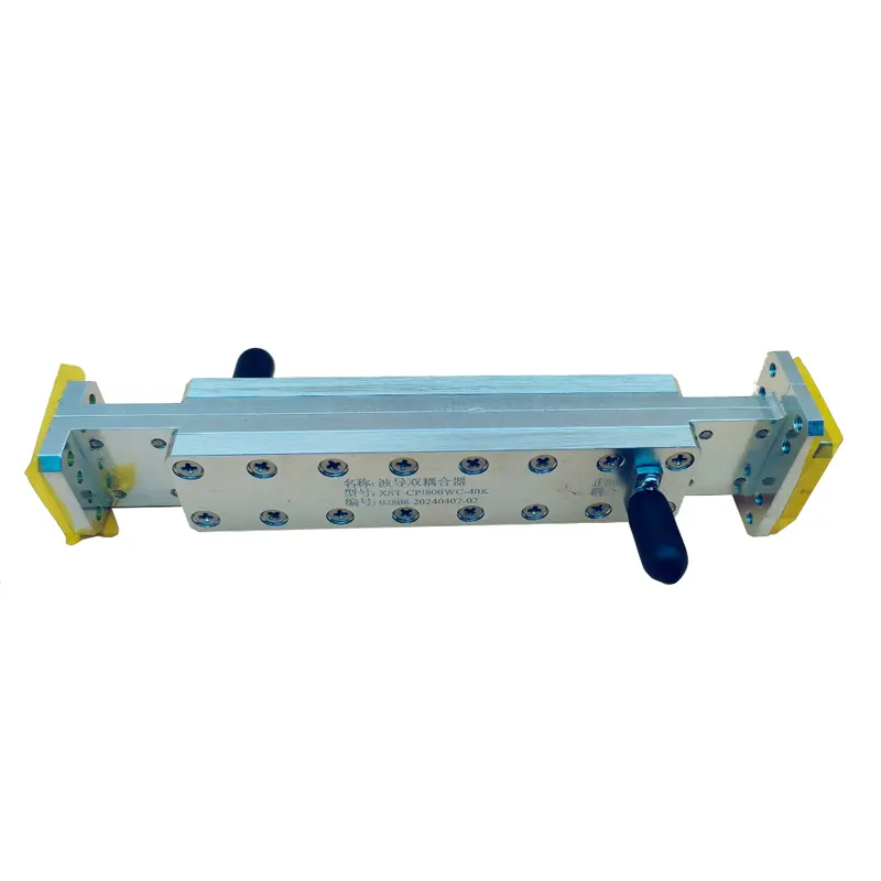
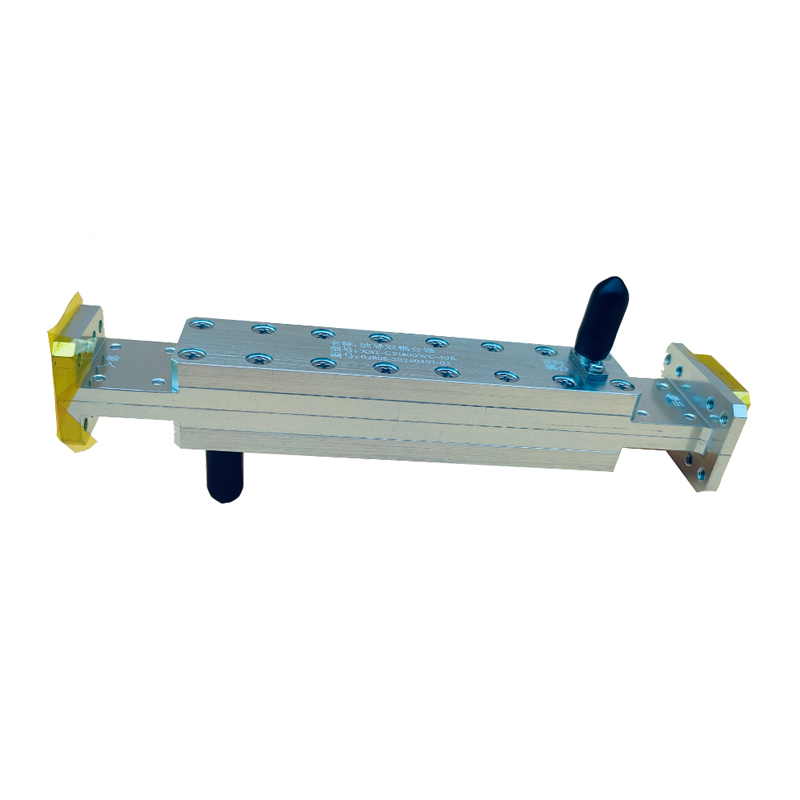
1. The Waveguide Dual Coupler ensures that the phase and amplitude of the signal remain highly stable during transmission.
2. Waveguide Dual Couplers are characterised by low insertion and reflection losses.
3. Waveguide Dual Couplers realise various coupling methods between two outputs, such as complete coupling, partial coupling and over-coupling, by adjusting the position between two holes.
Series of indicators
The following are some of our waveguide dual coupler series indicators, if you have more needs, welcome to consult.
| Product Model | Operating Frequency | Bandwidth | Insertion Loss (dB) | Standing Wave | Coupling (dB) | Directivity (dB) | Waveguide Type | Common Flange | |
| (GHz) | |||||||||
| XST-CP9□+coupling | 0.75-1.15 | 20% | 0.3 | 1.15 | 3-60 | 15-30 | WR975 | BJ9 | FDP/FDM |
| XST-CP12□+coupling | 0.96-1.46 | 20% | 0.3 | 1.15 | 3-60 | 15-30 | WR770 | BJ12 | FDP/FDM |
| XST-CP14□+coupling | 1.13-1.73 | 20% | 0.3 | 1.1 | 3-60 | 15-30 | WR650 | BJ14 | FDP/FDM |
| XST-CP18□+coupling | 1.45-2.20 | 20% | 0.3 | 1.1 | 3-60 | 15-30 | WR510 | BJ18 | FDP/FDM |
| XST-CP22□+coupling | 1.72-2.61 | 20% | 0.3 | 1.1 | 3-60 | 15-30 | WR430 | BJ22 | FDP/FDM |
| XST-CP26□+coupling | 2.17-3.30 | 20% | 0.3 | 1.1 | 3-60 | 15-30 | WR340 | BJ26 | FDP/FDM |
| XST-CP32□+coupling | 2.60-3.95 | 20% | 0.3 | 1.1 | 3-60 | 15-30 | WR284 | BJ32 | FDP/FDM |
| XST-CP40□+coupling | 3.22-4.90 | 20% | 0.3 | 1.1 | 3-60 | 15-30 | WR229 | BJ40 | FDP/FDM |
| XST-CP48□+coupling | 3.94-5.99 | 20% | 0.3 | 1.1 | 3-60 | 15-30 | WR187 | BJ48 | FDP/FDM |
| XST-CP58□+coupling | 4.64-7.05 | 20% | 0.3 | 1.1 | 3-60 | 15-30 | WR159 | BJ58 | FDP/FDM |
| XST-CP70□+coupling | 5.38-8.17 | 20% | 0.3 | 1.1 | 3-60 | 15-30 | WR137 | BJ70 | FDP/FDM |
| XST-CP84□+coupling | 6.57-9.99 | 20% | 0.3 | 1.1 | 3-60 | 15-30 | WR112 | BJ84 | FBP/FBM/FBE |
| XST-CP100□+coupling | 8.20-12.40 | 20% | 0.3 | 1.1 | 3-60 | 15-30 | WR90 | BJ100 | FBP/FBM/FBE |
| XST-CP120□+coupling | 9.84-15.0 | 20% | 0.3 | 1.1 | 3-60 | 15-30 | WR75 | BJ120 | FBP/FBM/FBE |
| XST-CP140□+coupling | 11.9-18.0 | 20% | 0.3 | 1.1 | 3-60 | 15-30 | WR62 | BJ140 | FBP/FBM/FBE |
| XST-CP180□+coupling | 14.5-22.0 | 20% | 0.3 | 1.1 | 3-60 | 15-30 | WR51 | BJ180 | FBP/FBM/FBE |
| XST-CP220□+coupling | 17.6-26.7 | 20% | 0.3 | 1.1 | 3-60 | 15-30 | WR42 | BJ220 | FBP/FBM/FBE |
| XST-CP260□+coupling | 21.7-33.0 | 20% | 0.3 | 1.15 | 3-60 | 15-30 | WR34 | BJ260 | FBP/FBM/FBE |
| XST-CP320□+coupling | 26.5-40.0 | 20% | 0.3 | 1.15 | 3-60 | 15-30 | WR28 | BJ320 | FBP/FBM/FBE |
| Product Model | Operating Frequency | Insertion Loss (dB) | Standing Wave | Coupling (dB) | Directivity (dB) | Waveguide Type | |
| (GHz) | |||||||
| XST-DRCP150□+coupling | 1.5-3.6 | 0.3 | 1.15 | 3-60 | 15-30 | 24JS1500 | WRD150D24 |
| XST-DRCP200□+coupling | 2-4.8 | 0.3 | 1.15 | 10-60 | 15-30 | 24JS2000 | WRD200D24 |
| XST-DRCP250□+coupling | 2.6-7.8 | 0.3 | 1.15 | 10-60 | 15-30 | 24JS2500 | WRD250D30 |
| XST-DRCP350□+coupling | 3.5-8.2 | 0.3 | 1.15 | 10-60 | 15-30 | 24JS3500 | WRD350D24 |
| XST-DRCP475□+coupling | 4.75-11 | 0.3 | 1.15 | 10-60 | 15-30 | 24JS4750 | WRD475D24 |
| XST-DRCP500□+coupling | 5.18 | 0.3 | 1.15 | 10-60 | 15-30 | 24JS5000 | WRD500D36 |
| XST-DRCP580□+coupling | 5.8-16 | 0.3 | 1.15 | 10-60 | 15-30 | 24JS15800 | WRD580D28 |
| XST-DRCP650□+coupling | 6.5-18 | 0.3 | 1.15 | 10-60 | 15-30 | 24JS6500 | WRD650D28 |
| XST-DRCP750□+coupling | 7.5-18 | 0.3 | 1.15 | 10-60 | 15-30 | 24JS7500 | WRD750D24 |
| XST-DRCP700□+coupling | 7-18.5 | 0.3 | 1.15 | 10-60 | 15-30 | 24JS7000 | WRD700D26 |
| XST-DRCP1100□+coupling | 11-26.5 | 0.3 | 1.15 | 10-60 | 15-30 | 24JS11000 | WRD1100C24 |
| XST-DRCP1800□+coupling | 18-40 | 0.3 | 1.15 | 10-60 | 15-30 | 24JS18000 | WRD1800C24 |
Performance characteristics
Waveguide dual couplers have a variety of performance characteristics, including coupling efficiency, operating bandwidth, isolation, insertion loss, and so on.
Coupling efficiency is one of the important indicators for evaluating the performance of the coupler, which indicates the proportion of energy transferred from one waveguide to another.
The operating bandwidth is the frequency range in which the coupler can work properly, which depends on the structural design and material properties of the coupling region.
Isolation reflects the coupler's ability to suppress uncoupled signals.
Insertion loss, on the other hand, indicates the energy loss of the signal as it passes through the coupler.
application example
Waveguide dual couplers have a wide range of applications in communication, radar, sensing and other fields.
In the communication system, the waveguide dual coupler can be used for signal splitting, combining and filtering and other functions.
In radar system, it can be used to achieve the beam scanning and pointing control of the antenna.
In the sensing system, waveguide dual coupler can be used to achieve the detection and measurement of the signal.